Seo Services

Featured Posts

[Travel][feat1]
The info

Definitions Concerning Magnetic Circuit

Definitions Concerning Magnetic Circuit

1.Magneto motive force (m.m.f.)

It drives or tends to drive flux through a magnetic circuit and corresponds to voltage (e.m.f.) in an electrical circuit.

M.M.F. is capable the work drained joules in carrying a unit magnetic pole once through the complete magnetic circuit. it's measured in ampere-turns.

 In fact, as p.d. between any 2 points is measured by the work drained carrying a unit charge from one points to a different, similarly, m.m.f. between 2 purposes is measured by the work drained joules in carrying a unit magnetic pole from one point to a different.

 2. Ampere-turns (AT). 

 it's the unit of magnetoelectric machine driving force (m.m.f.) and is given by the merchandise of variety of turns of a magnetic circuit and also the current in amperes in those turns.

 3. Reluctance. 

 it's the name given thereto property of a cloth that opposes the creation of magnetic flux in it.  It, in fact, measures the opposition offered to the passage of magnetic flux through a cloth and is analogous to resistance in an electrical circuit even in type.  Its units is AT/Wb.*


In alternative words, the reluctance of a magnetic circuit is that the range of amp-turns needed per weber of magnetic flux within the circuit.

 Since one AT/Wb = 1/henry, the unit of reluctance is “reciprocal henry.”

 4. Permeance. 

 it's reciprocal of reluctance and implies the case or readiness with that magnetic flux is developed. it's analogous to electrical phenomenon in electrical circuits. it's measured in terms of Wb/AT or henry.

 5. physical property/ Reluctivity

 it's specific reluctance and corresponds to resistance that is ‘specific resistance’.
Definitions Concerning Magnetic Circuit Definitions Concerning Magnetic Circuit Reviewed by I will write articles or blogs containing 500 words for you..... on April 11, 2019 Rating: 5

Force Between Two Parallel Conductors

Force Between Two Parallel Conductors

(i) Currents within the same direction


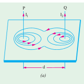
(i) Currents within the same direction. In Fig. 6.23 area unit shown 2 parallel conductors P and alphabetic character carrying currents I1 and I2 amperes within the same direction i.e. upwards. the sphere strength within the area between the 2 conductors is attenuate thanks to the 2 fields there being con to every alternative.

 Hence, the resultant field is as shown within the figure.  Obviously, the 2 conductors area unit attracted towards one another.


(ii) Currents in opposite directions.


(ii) Currents in opposite directions.  If, as shown in Fig. 6.24, the parallel conductors carry currents in opposite directions, then field intensity is exaggerated within the area between the 2 conductors thanks to the 2 fields being within the same direction there. 

Because of the lateral repulsion of the lines of the force, the 2 conductors expertise a mutual force of repulsion as shown individually in Fig. 6.24 (b).
Force Between Two Parallel Conductors Force Between Two Parallel Conductors Reviewed by I will write articles or blogs containing 500 words for you..... on April 11, 2019 Rating: 5

Weber and Ewing’s Molecular Theory

Weber and Ewing’s Molecular Theory

This theory was 1st advanced by Weber in 1852 and was, later on, more developed by Ewing in 1890. the fundamental assumption of this theory is that molecules of all substances ar inherently magnets in themselves, every having a N and S pole. 

In AN unmagnetised state, it's supposed that these tiny molecular  magnets exist all forms of haphazard manner forming additional or less closed loops (Fig. 6.5). per the laws of attraction and repulsion, these closed magnetic circuits ar glad internally, thus there's no resultant external magnetism exhibited by the iron bar. 

But once such AN iron bar is placed in a very force field or underneath the influence of a magnetising force, then these molecular magnets begin turning spherical their axes and make up one's mind themselves additional or less on straight lines parallel to the direction of the magnetising force.


This linear arrangement of the molecular magnets leads to N polarity at one finish of the bar and S polarity at the opposite (Fig. 6.6). because the tiny magnets flip additional nearly within the direction of the magnetising force, it needs additional and additional of this force to provide a given turning moment, therefore accounting for the magnetic saturation. 

On this theory, the physical phenomenon loss is meant to ensue to molecular friction of those turning magnets. owing to the restricted information of molecular structure out there at the time of Weber, it had been out of the question to clarify first, on why the molecules themselves ar magnets and second, why it's not possible to magnetise sure substances like wood etc. 

The first objection was explained by Ampere United Nations agency maintained that orbital movement of the electrons around the atom of a molecule implanted a flow of current that, thanks to its associated magnetic result, created the molecule a magnet.

Later on, it became troublesome to clarify the development of magnetism (shown by materials like water, quartz, silver and copper etc.) erratic behaviour of magnetic force (intensely magnetisable) substances like iron, steel, cobalt, nickel and a few of their alloys etc. and therefore the magnet (weakly magnetisable) substances like element and metallic element etc.

 Moreover, it had been asked : if molecules of all substances ar magnets, then why doesn't wood or air etc. become magnetic  ? All this has been explained satisfactorily by the atom-domain theory that has outdated the molecular theory. it's on the far side the scope of this book to travel into the main points of this theory.

 The interested reader is suggested to visit some customary book on magnetism.  However, it should simply be mentioned that this theory takes under consideration not solely the planetary motion of AN lepton however its rotation concerning its own axis likewise.  This latter rotation is termed ‘electron spin’.  The rotating mechanism behaviour of AN lepton provides rise to a moment of a magnet which can be either positive or negative.

 A substance is magnetic force or magnetic force consequently as there's AN way over unbalanced positive spins or negative spins.  Substances like wood or air ar non-magnetisable as a result of in their case, the positive and negative lepton spins ar equal, thus they cancel one another out.
Weber and Ewing’s Molecular Theory Weber and Ewing’s Molecular Theory Reviewed by I will write articles or blogs containing 500 words for you..... on April 11, 2019 Rating: 5
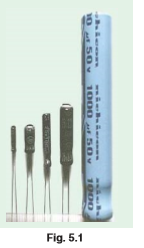
Capacitor

Capacitor

A capacitance basically consists of 2 conducting surfaces separated by a layer of Associate in Nursing insulating medium referred to as insulator.

 The conducting surfaces could also be within the sort of either circular (or rectangular) plates or be of spherical or cylindrical form. 

The purpose of a capacitance is to store power by static stress within the insulator (the word ‘condenser’ may be a name since a capacitance doesn't ‘condense’ electricity per se, it simply stores it).

 A parallel-plate capacitance is shown in Fig. 5.1.  One plate is joined to the positive finish of the provision and therefore the different to the negative finish or is earthed. it's {experimentally|by experimentation|through Associate in Nursing experiment} found that within the presence of an earthed plate B, plate A is capable of withholding a lot of charge than once B isn't there.

 once such a capacitance is communicate battery, there's a fugitive flow of electrons from A to B.  As negatively-charged electrons are withdrawn from A, it becomes positive and as these electrons collect on B, it becomes negative. 

Hence, a p.d. is established between plates A and B.


 The transient flow of electrons offers rise to charging current.  The strength of the charging current is most once the 2 plates ar dead however it then decreases and at last ceases once p.d. across the plates becomes slowly and slowly equal and opposite to the battery e.m.f.
Capacitor Capacitor Reviewed by I will write articles or blogs containing 500 words for you..... on April 11, 2019 Rating: 5

Synchronous Speed

Synchronous Speed 

The rotating magnetic field made by 3 section windings may are made by rotating a permanent magnet’s north and South Pole at synchronous speed, (shown as N and S at the ends of the flux phasors in Figures twenty two.1(b), (c) and (d)). For this reason, it's referred to as a 2-pole system And an induction motor victimization 3 section windings solely is termed a 2-pole induction motor.


If six windings displaced from each other by 60° area unit used, as shown in Figure twenty two.3(a), by drawing the present and resultant magnetic field diagrams at numerous time values,

 it should be shown that one cycle of the provision current to the mechanical device windings causes the magnetic field to maneuver through 0.5 a revolution. the present distribution within the mechanical device windings area unit shown in Figure twenty two.3(a), for the time t shown in Figure twenty two.3(b).


 It is seen that for 6 windings on the mechanical device, the magnetic flux made is that the same as that made by rotating 2 magnet north poles and 2 magnet south poles at synchronous speed. this is often referred to as a 4-pole system And an induction motor victimization six section windings is termed a 4-pole induction motor.

By increasing variety|the amount|the quantity} of section windings the quantity of poles is multiplied to any even number.

 In general, if f is that the frequency of the currents within the mechanical device windings and therefore the mechanical device is wound to be appreciate p pairs of poles, the speed of revolution of the rotating magnetic field, i.e., the synchronous speed, ns is given by:


Synchronous Speed  Synchronous Speed Reviewed by I will write articles or blogs containing 500 words for you..... on April 11, 2019 Rating: 5

Production of a Rotating Magnetic Field

Production of a Rotating Magnetic Field

When a three-phase offer is connected to symmetrical three-phase windings, the currents flowing within the windings manufacture a magnetic field. This magnetic field is constant in magnitude and rotates at constant speed as shown below, and is termed the synchronous speed.

With respect to Figure twenty two.1, the windings area unit described by 3 single-loop conductors, one for every part, marked RSRF, YSYF and BSBF, the S and F signifying begin and finish. In follow, every part winding includes several turns and is distributed round the stator; the single-loop approach is for clarity solely.

When the mechanical device windings area unit connected to a three-phase offer, the present flowing in every winding varies with time and is as shown in Figure twenty two.1(a). If the worth of current during a winding is positive, the idea is created that it flows from begin to finish of the winding, i.e., if it's the red part, current flows from RS to RF, i.e. aloof from the viewer in RS and towards the viewer in RF.

When the worth of current is negative, the idea is created that it flows from finish to begin, i.e. towards the viewer in Associate in Nursing ‘S’ winding Associate in Nursingd aloof from the viewer in an ‘F’ winding. At time, say t1, shown in Figure twenty two.1(a), the present flowing within the red part could be a most positive worth. At an equivalent time, t1, the currents flowing within the yellow and blue phases area unit each zero.5 times the utmost worth and area unit negative.

 the present distribution within the mechanical device windings is so as shown in Figure twenty two.1(b), during which current flows aloof from the viewer, (shown as ) inRS since it's positive, however towards the viewer (shown as þ ) in YS and bachelor's degree, since these area unit negative. The ensuing magnetic field is as shown, thanks to the ‘solenoid’ action and application of the corkscrew rule.


 A brief time later at time t2, the present flowing within the red part has fallen to regarding zero.87 times its most worth and is positive, the present within the yellow part is zero and also the current within the blue part is regarding zero.87 times its most worth and is negative. thence the currents and resultant magnetic field area unit as shown in Figure twenty two.1(c). At time t3, the currents within the red and yellow phases area unit zero.5 of their most worths and also the current within the blue part could be a most negative value. The currents and resultant magnetic field area unit as shown in Figure twenty two.1(d).

 Similar diagrams to work twenty two.1(b), (c) and (d) will be created for all time values and these would show that the magnetic field travels through one revolution for every cycle of the provision voltage applied to the mechanical device windings. By considering the flux values instead of the present values, it's shown below that the rotating magnetic field contains a constant worth of flux.

The 3 coils shown in Figure twenty two.2(a), area unit connected in star to a three-phase offer. Let the positive directions of the fluxes created by currents flowing within the coils, be A, B and C severally. The directions of A, B and C don't alter, however their magnitudes area unit proportional to the currents flowing within the coils at any explicit time. At time t1, shown in Figure twenty two.2(b), the currents flowing within the coils are:

 iB, a most positive worth, i.e., the flux is towards purpose P; American state and iC, 0.5 the utmost worth and negative, i.e., the flux is aloof from purpose P.

 These currents bring about to the magnetic fluxes A, B and C, whose magnitudes and directions area unit as shown in Figure twenty two.2(c). The resultant flux is that the phasor add of A, B and C, shown as eight in Figure twenty two.2(c). At time t2, the currents flowing are:


Production of a Rotating Magnetic Field Production of a Rotating Magnetic Field Reviewed by I will write articles or blogs containing 500 words for you..... on April 11, 2019 Rating: 5

Speed Control of D.C. Motors

Speed Control of D.C. Motors

Shunt-wound motors

The speed of a shunt-wound d.c. motor, n, is proportional to VIaRa/8 (see equation (21.9)). The speed is varied either by varied the worth of flux, 8, or by varied the worth of Ra. the previous is achieved by employing a resistance nonparallel with the field winding, as shown in Figure twenty one.29(a) and such a electrical device is termed the shunt field regulator. because the price of resistance of the shunt field regulator is redoubled, the worth of the field current, If, is minimized.


This ends up in a decrease within the price of flux, 8, and thus a rise within the speed, since n/1/8. therefore solely speeds on top of that given while not a shunt field regulator is obtained by this technique. Speeds below those given by VIaRa/8 are obtained by increasing the resistance within the coil circuit, as shown in Figure twenty one.29(b), where


Since electrical device R is nonparallel with the coil, it carries the complete coil current and ends up in massive|an out sized|an over sized} power loss in large motors wherever a substantial speed reduction is needed for long periods. These ways of speed management square measure incontestible within the following worked drawback.


Series-wound motors

 The speed control of series-wound motors is achieved using either(a) field resistance, or (b) coil resistance techniques.

(a) The speed of a d.c. series-wound motor is given by:

where k may be a constant, V is that the terminal voltage, R is that the combined resistance of the coil and series field and eight is that the flux.

 Thus, a discount in flux ends up in a rise in speed. this is often achieved by putt a variable resistance in parallel with the field winding and reducing the field current, and therefore flux, for a given worth of offer current. A circuit diagram of this arrangement is shown in Figure twenty one.30(a).
A resistor connected in parallel with the series-wound field to regulate speed is termed a diverter. Speeds higher than those given with no diverter square measure obtained by this technique. downside twenty nine below demonstrates this technique.

 (b) Speeds below traditional square measure obtained by connecting a resistor nonparallel with the field winding and coil circuit, as shown in Figure twenty one.30(b). This effectively will increase the worth of R within the equation


Speed Control of D.C. Motors  Speed Control of D.C. Motors Reviewed by I will write articles or blogs containing 500 words for you..... on April 11, 2019 Rating: 5
ads 728x90 B
Powered by Blogger.