
D.c. generators
D.c. generators ar classified per the strategy of their field excitation. These groupings are:
(i) Separately-excited generators
Separately-excited generators, wherever the field winding is connected to a supply of provide aside from the coil of its own machine.
(ii) Self-excited generators
Self-excited generators, wherever the field winding receives its provide from the coil of its own machine, and that ar sub-divided into (a) shunt, (b) series, and (c) compound wound generators.
Types of d.c. generator and their characteristics
(a) Separately-excited generator

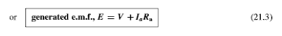
A typical separately-excited generator circuit is shown in Figure twenty one.5. once a load is connected across the coil terminals, a load current Hawkeye State can flow. The terminal voltage V can fall from its open-circuit e.m.f. E thanks to a V drop caused by current flowing through the coil resistance, shown as Ra, i.e.,

Characteristics
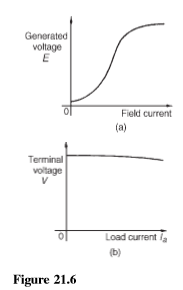
The 2 principal generator characteristics ar the generated voltage/field current characteristics, referred to as the open-circuit characteristic and therefore the terminal voltage/load current characteristic, referred to as the load characteristic.
A typical separately-excited generator open-circuit characteristic is shown in Figure twenty one.6(a) and a typical load characteristic is shown in Figure twenty one.6(b).
A separately-excited generator is employed solely in special cases, like once a large variation in terminal p.d. is needed, or once actual management of the field current is important. Its disadvantage lies in requiring a separate supply of DC.
(b) Shunt-wound generator
during a shunt wound generator the field winding is connected in parallel with the coil as shown in Figure twenty one.7. The field winding includes a comparatively high resistance and so the present carried is simply a fraction of the coil current.
Characteristics
The generated e.m.f., E, is proportional to 8ω, thus at constant speed, since ω D2n, E/8. conjointly the flux eight is proportion to field current If till magnetic saturation of the iron circuit of the generator happens. thus the electrical circuit characteristic is as shown in Figure twenty one.9(a).
As the load current on a generator having constant field current and running at constant speed will increase, the worth of coil current will increase, thus the coil V drop, IA Ra will increase. The generated voltage E is larger than the terminal voltage V and therefore the voltage equation for the coil circuit is VDEIaRa. Since E is constant, V decreases with increasing load. The load characteristic is as shown in Figure twenty one.9(b). In apply, the autumn in voltage is regarding 100 percent between no-load and full-load for several d.c. shunt-wound generators.
The shunt-wound generator is that the sort most employed in apply, however the load current should be restricted to worth|a worth|a price} that's well below the most value. This then avoid successive variation of the terminal voltage. Typical applications square measure with battery charging and motor automotive generators.
(c) Series-wound generator
In the series-wound generator the field winding is connected nonparallel with the coil as shown in Figure 21.10.
Characteristic
The load characteristic is that the terminal voltage/current characteristic. The generated e.m.f. E, is proportional to 8ω and at constant speed ω (D 2n) could be a constant. so E is proportional to eight. For values of current below magnetic saturation of the yoke, poles, air gaps and coil core, the flux eight is proportional to this, hence E/I. For values of current on top of those needed for magnetic saturation, the generated e.m.f. is more or less constant. The values of field resistance and coil resistance during a series wound machine ar tiny, therefore the terminal voltage V is incredibly nearly capable E. A typical load characteristic for a series generator is shown in Figure twenty one.11.
In a series-wound generator, the field winding is nonparallel with the coil and it's unimaginable to possess a worth of field current once the terminals ar open circuited, so it's unimaginable to get Associate in Nursing electrical circuit characteristic.
Series-wound generators ar seldom utilized in observe, however is used as a ‘booster’ on d.c. transmission lines.
(d) Compound-wound generator
In the compound-wound generator 2 ways of association area unit used, each having a combination of shunt and series windings, designed to mix the benefits of every. Figure 21.12(a) shows what's termed a long shunt compound generator, and 21.12(b) shows a short-shunt Figure 21.1 compound generator. The latter is that the most usually used sort of d.c. generator.
Characteristics
In cumulative-compound machines the magnetic flux made by the series and shunt fields are additive. enclosed during this cluster are over-compounded, level-compounded and under-compounded machines—the degree of combination obtained betting on the amount of turns of wire on the series winding.
A large variety of series winding turns leads to associate degree over-compounded characteristic, as shown in Figure 21.14, during which the full-load terminal voltage exceeds the no-load voltage. A level-compound machine offers a full-load terminal voltage that is up to the no-load voltage, as shown in Figure 21.14.
associate degree under-compounded machine offers a full-load terminal voltage that is a smaller amount than the no-load voltage, as shown in Figure 21.14. but even this latter characteristic may be a very little higher than that for a shunt generator alone.

D.c. generators
 Reviewed by I will write articles or blogs containing 500 words for you.....
on
April 11, 2019
Rating:
Reviewed by I will write articles or blogs containing 500 words for you.....
on
April 11, 2019
Rating:
Reviewed by I will write articles or blogs containing 500 words for you.....
on
April 11, 2019
Rating:


No comments: