
D.C. Machines
Introduction
When the input to Associate in Nursing electrical machine is voltage, (seen as applying a voltage to the electrical terminals of the machine), and therefore the output is energy, (seen as a rotating shaft), the machine is termed an electrical motor. therefore an electrical motor converts voltage into energy.
once the input to Associate in Nursing electrical machine is energy, (seen as, say, a diesel engine, coupled to the machine by a shaft), and therefore the output is voltage, (seen as a voltage showing at the electrical terminals of the machine), the machine is termed a generator. Thus, a generator converts energy to voltage.
The action of a commutator
In an electrical motor, conductors rotate in a very uniform magnetic field. A single-loop conductor mounted between permanent magnets is shown in Figure twenty one.1. A voltage is applied at points A and B in Figure twenty one.1(a).

Figure. 21.1
A force, F, acts on the loop because of the interaction of the magnetic field of the permanent magnets and also the magnetic field created by the present flowing within the loop. This force is proportional to the flux density, B, the present flowing, I, and also the effective length of the conductor, l, i.e. FDBIl.
The force is formed of 2 elements, one acting vertically downwardly because of the present flowing from C to D and also the different acting vertically upwards because of the present flowing from E to F (from Fleming’s paw rule). If the loop is unengaged to rotate, then once it's turned through 180°, the conductors area unit as shown in Figure twenty one.1(b). For rotation to continue within the same direction, it's necessary for the present flow to be as shown in Figure twenty one.1(b), i.e. from D to C and from F to E. This apparent reversal within the direction of current flow is achieved by a method referred to as commutation. With relation to Figure twenty one.2(a),
When an immediate voltage is applied at A and B, then because the single-loop conductor rotates, current flow can continuously be removed from the electric switch for the a {part of} the conductor adjacent to the N-pole and towards the electric switch for the part of the conductor adjacent to the S-pole. therefore the forces act to present continuous rotation in AN anti-clockwise direction. The arrangement shown in Figure twenty one.2(a) is named a ‘two-segment’ electric switch and also the voltage is applied to the rotating segments by stationary brushes, (usually carbon blocks), that slide on the electric switch material, (usually copper), once rotation takes place.
In follow, there area unit several conductors on the rotating a part of a d.c. machine and these area unit hooked up to several electric switch segments. A schematic diagram of a multi-segment electric switch is shown in Figure twenty one.2(b).
D.c. machine construction

The basic components of any d.c. machine area unit shown in Figure twenty one.3, and comprise:
(a) a stationary half known as the mechanical device having,
(i) a steel ring known as the yoke, to that area unit connected
(ii) the magnetic poles, around that area unit the
(iii) field windings, i.e. several turns of a conductor wound around the pole core; current passing through this conductor creates Associate in Nursing magnet, (rather than the permanent magnets shown in Figures twenty one.1 and 21.2),
(b) a rotating half known as the coil mounted in bearings housed within the mechanical device and having,Figure 21.3
(iv) a laminated cylinder of iron or steel known as the core, on that teeth area unit move house the
(v) coil winding, i.e. one or multi-loop conductor system and
(vi) the electric switch, (see Section twenty one.2).
Armature windings is divided into 2 teams, looking on however the wires area unit joined to the electric switch. These area unit known as wave windings and lap windings.
(a) In wave windings there area unit 2 methods in parallel no matter the amount of poles, every path provision 0.5 the entire current output. Wave wound generators turn out high voltage, low current outputs.
(b) In lap windings there area unit as several methods in parallel because the machine has poles. the entire current output divides equally between them. Lap wound generators turn out high current, low voltage output.
Shunt, series and compound windings
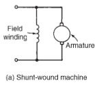
When the field winding of a d.c. machine is connected in parallel with the coil, as shown in Figure 21.4(a), the machine is claimed to be shunt wound. If the field winding is connected asynchronous with the coil, as shown in Figure 21.4(b), then the machine is claimed to be series wound. A compound wound machine contains a combination of series and shunt windings.

Depending on whether or not the electrical machine is series wound, shunt wound or compound wound, it behaves otherwise once a load is applied. The behaviour of a d.c. machine below varied conditions is shown by suggests that of graphs, known as characteristic curves or simply characteristics. The characteristics shown within the following sections ar theoretical, since they neglect the consequences of coil reaction.

Armature reaction is that the impact that the magnetic field created by the coil current has on the magnetic field created by the field system. in an exceedingly generator, coil reaction ends up in a reduced output voltage, and in an exceedingly motor, coil reaction ends up in exaggerated speed.
some way of overcoming the impact of coil reaction is to fit compensating windings, settled in slots within the pole face.
D.C. Machines
 Reviewed by I will write articles or blogs containing 500 words for you.....
on
April 10, 2019
Rating:
Reviewed by I will write articles or blogs containing 500 words for you.....
on
April 10, 2019
Rating:
Reviewed by I will write articles or blogs containing 500 words for you.....
on
April 10, 2019
Rating:


No comments: